Home
› Honeywell T8775C1005 Wiring Diagram / T8775C1005 - Honeywell T8775C1005 - Round Non-Programmable, 1H/1C, Digital Thermostat / For the y, y1, and y2 wires, y or y1 will go to the y terminal, and y2 will go to the y2 terminal.
Honeywell T8775C1005 Wiring Diagram / T8775C1005 - Honeywell T8775C1005 - Round Non-Programmable, 1H/1C, Digital Thermostat / For the y, y1, and y2 wires, y or y1 will go to the y terminal, and y2 will go to the y2 terminal.
Honeywell T8775C1005 Wiring Diagram / T8775C1005 - Honeywell T8775C1005 - Round Non-Programmable, 1H/1C, Digital Thermostat / For the y, y1, and y2 wires, y or y1 will go to the y terminal, and y2 will go to the y2 terminal.. *never attach wires to both the b and o. Use only letter designations to identify wire types. Ensure that each numbered, lettered or coloured wire is connected to the correct terminal in the junction box. Within this phase, the device will show nest wiring diagram honeywell. Premier white 1heat/1 cool stage digital round™ thermostat with manual changeover and r,rc,o,b,g,y,w terminals for 24 vac gas, oil and electric heating with cooling, including 1 heat/1 cool heat pumps
See the diagram below for what each wire controls on your system: Pull the wires through the wiring hole on the bottom left side of the cover ring. The honeywell home trademark is used under license from honeywell international inc. 8 through 11 for typical wiring diagrams. This article series explains the basics of wiring connections at the thermostat for heating, heat pump, or air conditioning systems.
Honeywell Thermostat Selection Guide from home-appliance.filemanual.com After completing this, you can also prepare the application for remote control if desired. Put the jumper back in rc and rh and that should do it. See the diagram below for what each wire controls on your system: Premier white 1heat/1 cool stage digital round™ thermostat with manual changeover and r,rc,o,b,g,y,w terminals for 24 vac gas, oil and electric heating with cooling, including 1 heat/1 cool heat pumps If e and aux do not each have a wire connected, use a small piece of wire to connect them to each other. Ensure that each numbered, lettered or coloured wire is connected to the correct terminal in the junction box. *never attach wires to both the b and o. The thermostat uses 1 wire to control each of your hvac system's primary functions, such as heating, cooling, fan, etc.
Gently pull the wire bundle out of the wall to check for unused wires.
This wire will go to the g terminal on your new thermostat. After completing this, you can also prepare the application for remote control if desired. Room thermostat installation & wiring guide: There might be an extra wire pushed into the wall or wrapped around the wire bundle. S for deviations to these wiring diagrams or the job specific wiring diagrams, consult the factory. Older honeywell thermostat wiring diagrams. 5 connect wires (alternate wiring) if labeled wire does not match any terminal designation, see diagram below. Do not use c, c1 or x wire. Use a screwdriver to loosen screws, insert wires into hole under screw, then tighten screws until wire is secure. Connect one.ct87a,b,j roundfi thermostat 6 wire the thermostat 1. Variety of honeywell th9421c1004 wiring diagram. The thermostat uses 1 wire to control each of your hvac system's primary functions, such as heating, cooling, fan, etc. 8 through 13 wiring diagrams.
When nest thermostat was detected, affirm the machine and continue setting the temperature. There might be an extra wire pushed into the wall or wrapped around the wire bundle. The honeywell home trademark is used under license from honeywell international inc. Match each labeled wire with same letter on new thermostat. Room thermostat installation & wiring guide:
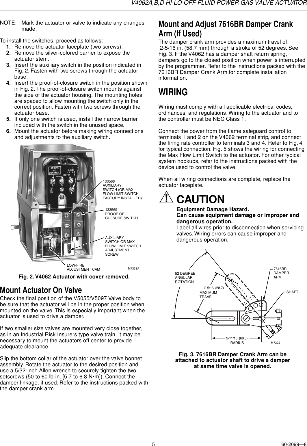
Honeywell Thermostat V4062B Users Manual 60 2099 V4062A,B,D Hi Lo Off Fluid Power Gas Valve Actuator from usermanual.wiki Location (check the appropriate wiring diagram). Room thermostat installation & wiring guide: After completing this, you can also prepare the application for remote control if desired. 13, beginning on page 7, •. If all is good, only push to continue. The thermostat uses 1 wire to control each of your hvac system's primary functions, such as heating, cooling, fan, etc. Place a jumper (piece of wire) between y and 8 through 11 for typical wiring diagrams.
Do not use b wire if you already have o wire.
Our wiring diagrams section details a selection of key wiring diagrams focused around typical sundial s and y plans. Location (check the appropriate wiring diagram). Do not use b wire if you already have o wire. Connect one.ct87a,b,j roundfi thermostat 6 wire the thermostat 1. For the y, y1, and y2 wires, y or y1 will go to the y terminal, and y2 will go to the y2 terminal. There might be an extra wire pushed into the wall or wrapped around the wire bundle. 8 through 13 wiring diagrams. When nest thermostat was detected, affirm the machine and continue setting the temperature. Let's take a look at the g wire. Room thermostat installation & wiring guide: Place a jumper (piece of wire) between y and Premier white 1heat/1 cool stage digital round™ thermostat with manual changeover and r,rc,o,b,g,y,w terminals for 24 vac gas, oil and electric heating with cooling, including 1 heat/1 cool heat pumps Contains all the essential wiring diagrams across our range of heating controls.
8 through 13 wiring diagrams. 8 through 13 wiring diagrams. Alternate wiring quick installation guide connect wires (cont'd) alternate wiring if a labeled wire does not match any terminal designation, see diagram below. View online or download honeywell the digital round ct8775c owner's manual Wiring diagram for t7770g10xx wall modules wired to excel 600/500/100/80/20.
Honeywell CT8775C The Digital Round Manual Thermostat HEAT and COOL NOS 85267244152 | eBay from i.ebayimg.com Page 7 tb6575/tb8575 suitepro™ digital fan coil thermostats thermostat wiring diagrams l (hot) the figures in this section illustrate typical wiring for: Older honeywell thermostat wiring diagrams. Ensure that each numbered, lettered or coloured wire is connected to the correct terminal in the junction box. Use a screwdriver to loosen screws, insert wires into hole under screw, then tighten screws until wire is secure. View online or download honeywell the digital round ct8775c owner's manual S for deviations to these wiring diagrams or the job specific wiring diagrams, consult the factory. Wiring diagram for t7770g10xx wall modules wired to excel 600/500/100/80/20. When nest thermostat was detected, affirm the machine and continue setting the temperature.
Wiring diagram was not supplied in the main instruction booklet, for a cooling only setup.
Older honeywell thermostat wiring diagrams. Wrap bare end of wire with electrical tape. 8 through 11 for typical wiring diagrams. Push any excess wire back into the wall opening. Wrap bare end of wire with electrical tape. Within this phase, the device will show nest wiring diagram honeywell. C honeywell v8043 zone valves 1 th tr transformer r 24. *never attach wires to both the b and o. Wiring diagram was not supplied in the main instruction booklet, for a cooling only setup. *never attach wires to both the b and o terminals. S for deviations to these wiring diagrams or the job specific wiring diagrams, consult the factory. Mount thermostat base ignore wire colors: Location (check the appropriate wiring diagram).